External MPPT Instructions
EXTERNAL MPPT DIAGRAM
A: Red Anderson connector. This plugs into the Titan Solar Generator (Aux port, or AC charging port)
B: Your MPPT display screen. The display screen shows settings and information. Later down we will show you how to change what information you can view, and how to change the settings.
C: MC4 solar connector cables. These are the cables that you will connect your solar array to, which will give charge to your MPPT, and sequentially, charge your Solar Generator.
D: LED indicators. There are three LED indicator lights. From left to right, they are labeled ERROR, CHARGE, and LOAD. If the ERROR LED is lit, it indicates a fault in the external MPPT. When the CHARGE LED is lit, it indicates that the external MPPT is providing charge to your Solar Generator. When the LOAD LED is lit, it indicates that there is a load present.
E: Preference/action buttons. These buttons are used to navigate the settings and options of the external MPPT. The top two buttons are the “UP” and “DOWN” buttons, and the bottom two buttons are “ESC” and “SET”. These buttons are used to navigate, and change the values on different settings in the external MPPT.
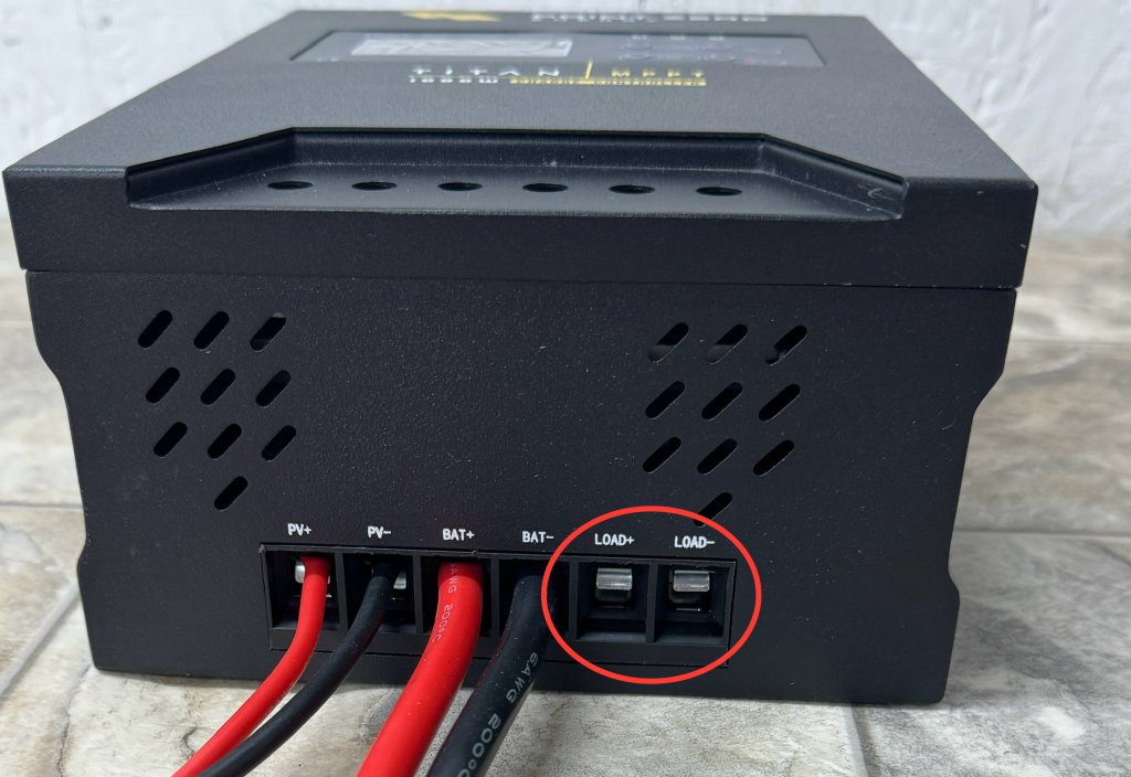
F: Wire connection ports. This area is where both the MC4 solar connectors, and the red Anderson connector wires connect into the external MPPT. To the right of where the Anderson connector cables connect into the MPPT, you will see the DC output terminal, which you are able to connect to, which is shown in the picture below.
Connecting your external MPPT to your Titan Solar Generator
What you will first need to do is mount your external MPPT to the wall. In your MPPT packaging, there should be hooks which you can attach to your external MPPT for mounting it to the wall. Avoid installing the external MPPT in direct sunlight, high temperatures, or around areas where there is easy access to water. Also, make sure that there is adequate ventilation around the external MPPT. We recommend a minimum of 6 inches of ventilation around each edge of the MPPT.
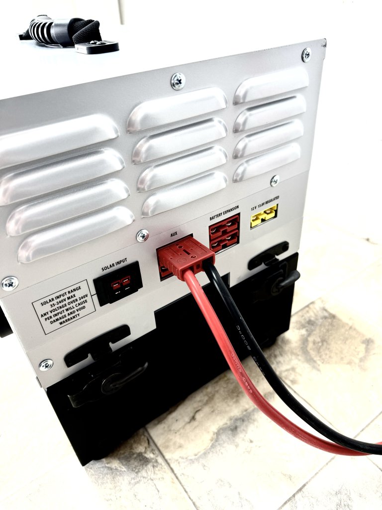
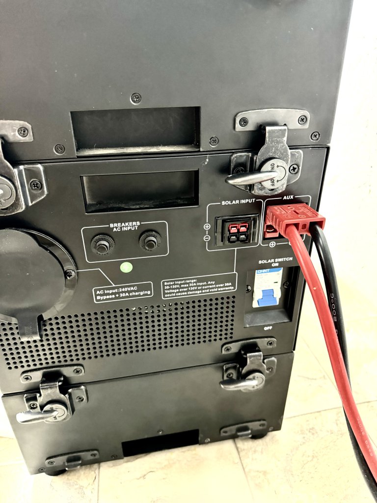
Once your external MPPT is mounted, you will then connect your external MPPT to your Titan Solar Generator. You can do this by plugging in the red Anderson connector on your external MPPT, into one of your Titan Aux ports, or the AC charging port. This will then power on your external MPPT. See pictures below.
Next, you will connect the MC4 solar wires from your solar setup/array, to the MC4 connectors on your external MPPT, shown in the picture below.
Now, your external MPPT is fully connected. Below is what it should look like with everything connected.
Now with everything connected, your external MPPT will begin providing charge to your Titan Solar Generator.
External MPPT Display Information and Settings
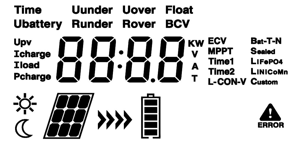
Below is a picture of all the display icons on the external MPPT, and what they mean. Below is also all of the external MPPT display information, and all of the settings and their meanings.
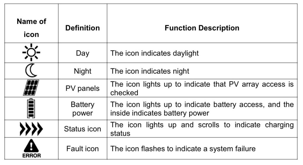
Display Icons
Display Icon Information
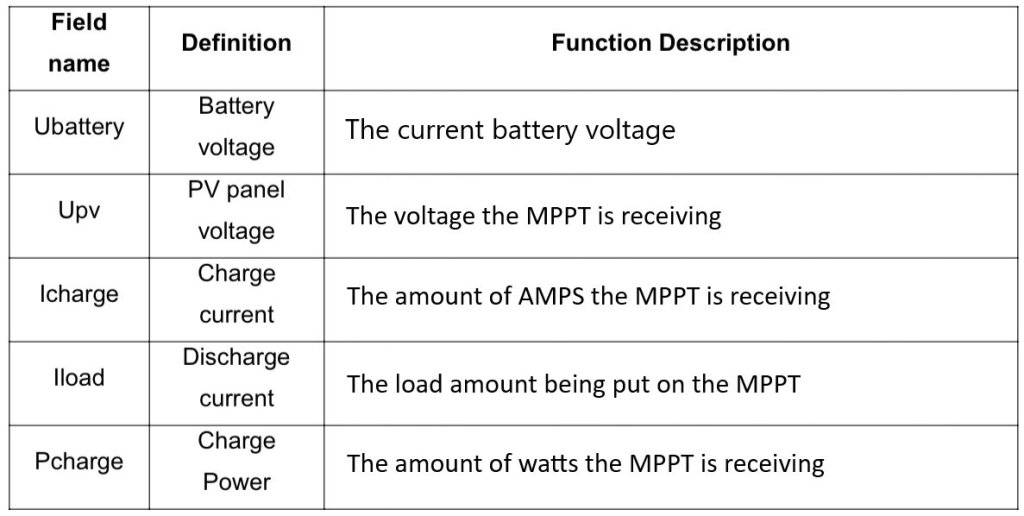
Display Information
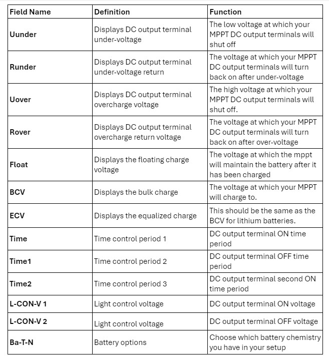
External MPPT Settings
NOTE: We do not recommend change any of the following settings : Time, Time 1, Time 2, L-CON-V, and Ba-T-N
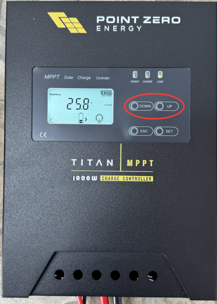
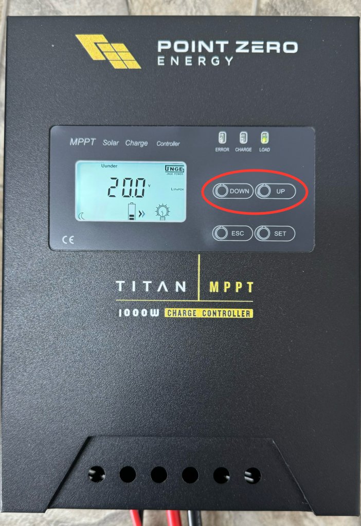
While on the main screen of your MPPT, you can navigate the screen information by pressing either the “UP” or “DOWN” buttons, shown in the image below.
These display options are not settings, and therefore cannot be changed. The options simply show you information from the MPPT.
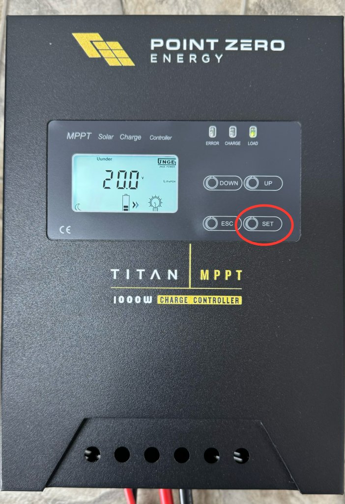
You can go through the internal settings of the external MPPT by pressing the “SET” button. Each time you click the “SET” button, it will go to the next setting.

Changing the settings on the external MPPT
Your external MPPT will already come with the correct settings. These settings do not need to be changed. However if you do want to change these settings, you can follow these steps.
- Press the “SET” button until you have arrived on the setting you would like to change

2. Press the “UP” or “DOWN” buttons to change the value of the setting to the desired amount
3. Once the desired value of the setting is reached, click the “SET” button again
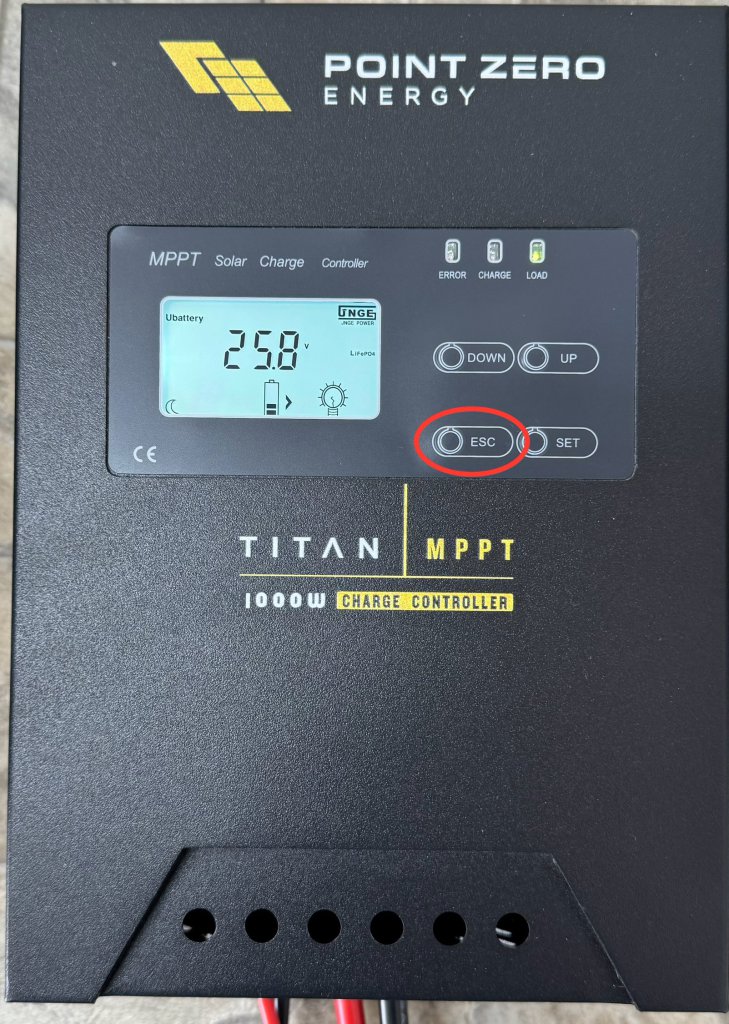
4. Click the “ESC” button. This will take you back to the main screen.
The desired setting has now been changed. You can check by clicking the “SET” button until you get to the setting you just changed, to confirm that it has been changed.
If you would like to go back to the default settings, they are labeled underneath.
Uunder: 20.0v
Runder: 26.5v
Uover: 31.0v
Rover: 29.6v
Float: 27.2v
BCV: 28.8v
ECV: 28.8v
Time: 24
Time1: 00
Time2: 00
L-CON-V: 1 5.0v 2 6.0v